We’ve written before about the Maiden Lane Bridge, giving some of the history of what was the second bridge built across the Hudson at Albany. In that story, we included a number of specifications that were published when the contract to build the bridge was awarded to Charles Newman of Hudson in 1870. Now we find it’s unclear what happened to that contract, because in 1872 the British journal Engineering provided a very detailed description of the bridge as it was built, and credits it to the firm of Clarke, Reeves, and Co. of the Phoenixville Iron Works. Their offices were listed as Philadelphia, but the foundry itself was about three blocks from Hoxsie’s current home in the lovely little borough of Phoenixville, PA. Any question about which account of the builder is quickly decided in favor of Clarke, Reeves from the litho provided in the journal, because the trusses of the bridge are clearly constructed from the patented Phoenix column.
As the Wikipedia entry explains, “The Phoenix Column, patented by Samuel Reeves in 1862, was a hollow cylinder composed of four, six, or eight wrought iron segments riveted together. The resulting column was much lighter and stronger than the solid cast iron columns of the day.”
In their 1873 album of designs, The Phoenixville Bridge-Works, Clarke, Reeves & Co., described their bridge Design H:
“This is our regular pattern of through pivot-bridges, with our patent turn-table, of a simple and effective construction. Where a pivot-pier has to be specially constructed, considerable economy will be obtained by carrying up a circular wall of masonry, and reducing the depth of iron ring . . . Our pivot-bridges have always given satisfaction; and we refer particularly to that over the Hudson River at Albany, belonging to the New York Central and Hudson, and the Boston and Albany Railroads, as a model of a quick-working and substantial pivot-bridge.”
Worthy of note, for those who aren’t fascinated by engineering specifications:
- There was very little wood, other than the cross-ties and the sidewalks. There was also no roof. Bridge roofing, and wooden construction, was the cause of the devastating fire in Troy in 1862, and while the replacement for that bridge was given a metal roof, the days of covered bridges were generally over, and making a rail bridge out of wood, once it was no longer necessary, was also recognized as unwise.
- While the swing bridge was operated by a steam engine, it could be hand-operated by two men using a lever turning gear.
- The machinery was to be coated with white lead and tallow. The rest of the bridge skipped the tallow.
The Maiden Lane bridge carried trains across the Hudson River from Dec. 28, 1871 until the closing of Union Station in 1968. Nothing was wrong with it, but it was in the way of progress in the form of I-787, and the entire span was demolished by January 1970.
The details below come from Engineering, July 5, 1872. To the extent that they differ from what was reported in 1870, we’ll assume these were the as-built specifications.
BRIDGE OVER THE HUDSON RIVER.
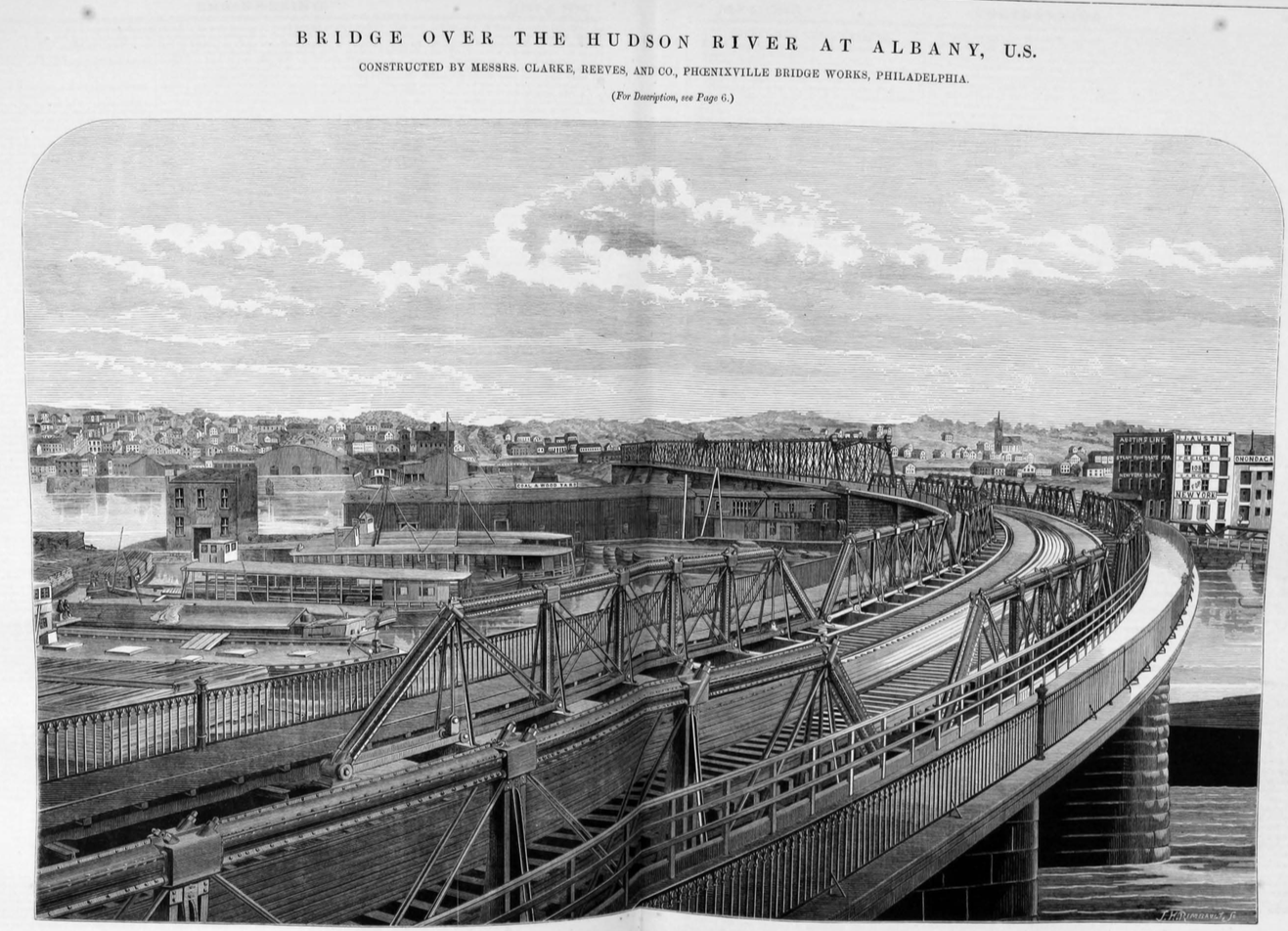
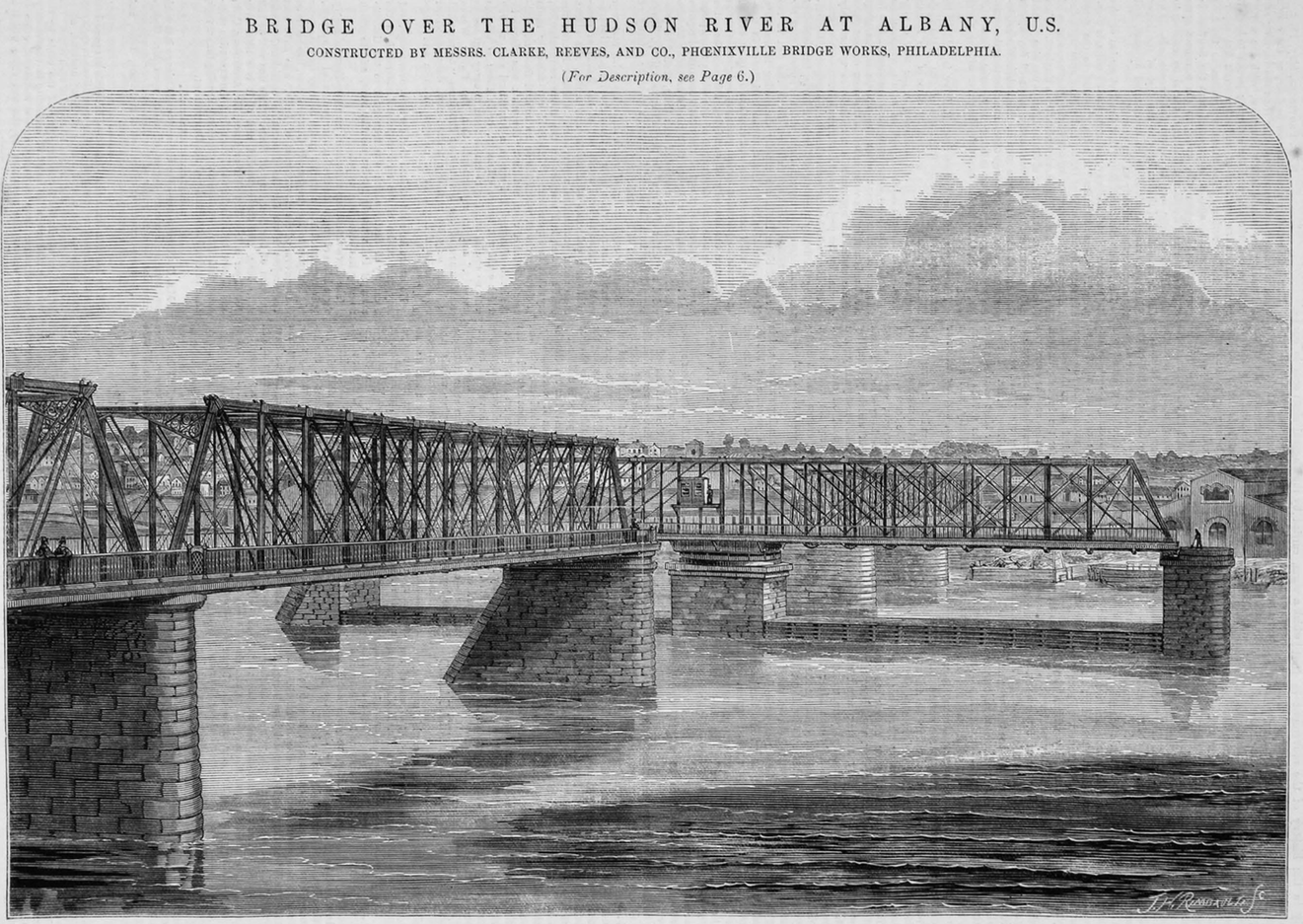
We publish, this week, a two-page engraving, together with another illustration on page 4, of a fine railway bridge recently erected across the Hudson River, at Albany, by Messrs. Clarke, Reeves, and Co., of the Phoenixville Iron Works, Philadelphia. The bridge, which consists altogether of fifteen spans, and has a total length of 1740 ft., or nearly a third of a mile, was built under the following specification:
Specification.
- The arrangement and lengths of the spans of the bridge to be as follows: Crossing Maiden-lane one of 63 ft. and one of 70 ft.; Quay-street of 110 ft. Then, beginning at the west shore of the Albany Basin, there are to be seven spans of 70 ft. each, crossing the said Albany Basin on a curve of about 720 ft. radius to the Albany Pier; thence crossing the main channel of the river on a straight line; two spans of 185 ft., a swing bridge 274 ft. long, and two spans 185 ft. each, arranged in the order in which they are named – the length of spans given being from centre to centre of piers; and all of the piers and abutments being parallel to each other, and at right angles to the straight portion of the bridge.
- The superstructure to be entirely of wrought iron, except necessary bearing and joint blocks, which may be of cast iron, and to carry, at the bottom thereof, a double track railway, and also two sidewalks, each sidewalk being 6 ft. wide. The bridge to be built with two lines of main girders, 26 ft. apart in the clear on the straight portion of the bridge, and 27-1/2 ft. apart in the clear on the curved part.
- The several spans of the superstructure will be built in accordance with the general plans attached to and forming part of these specifications, and lettered and described as follows:
- Elevation of drawbridge, 274 ft. long
- Elevation of the fixed spans, 185 ft. long.
- Elevation of basin spans, 73 ft. long.
- Plan of cross beams of floor.
- The main girders of the bridge over the basin to be not more than 8 ft. in height, and those over the main channel not more than 25 ft. in height, outside measure. The depth of the floor must not exceed 2 ft. 10 in. from the under side of the track rail to the lowest points of the bridge.
- Both the cross beams and stringers of the railway floor to be of iron, leaving nothing to be of wood, except the cross-ties, upon which the rails are to be laid. The side walks to be outside of the trusses, and supported by continuations of the cross beams of the railway floor.
- The main girders of the bridge to be proportioned to carry a rolling load of 6000 lb. per lineal foot of bridge in addition to the weight of the superstructure, without subjecting the iron to a greater tensile strain than 10,000 lb. per square inch of parts in tension, and 9500 lb. compression per square inch sectional area of upper chords.
- The floor system to be proportioned to carry any load that can be imposed upon any cross beam or stringer by passing locomotives with driving wheels, carrying 6 tones each, and geared 7 ft. 9 in. apart between centres, without exceeding the limits of stress above specified for the main girders. Shearing strains upon joint pieces shall not exceed 7500 lb. per square inch.
- Due provision to be made for the expansion and contraction of the main girders under changes of temperatures and the consequent tendency to movement upon the piers and abutments.
- The swing bridge must be made easily adjustable, so that any deflection of the ends, from any cause, may be readily corrected.
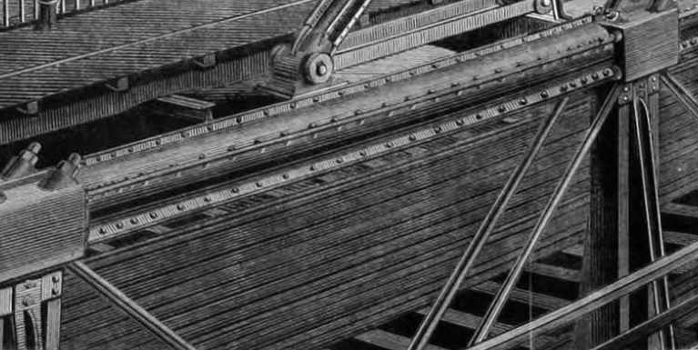
- The turntable shall be constructed upon the most approved plan, and of the best material and workmanship, to be operated by a suitable steam engine of ample power, with necessary machinery and gearing for operation of same, located on the top of the bridge over the turntable, and properly housed from the weather, with storage room for fuel, &c.
- The friction wheels or rollers, upon which the swing bridge is to revolve, shall be of an outside diameter of not less than 15 in., and of such number and iwdth of face that, when the whole weight of the swing bridge is distributed uniformly upon them, each wheel will carry a load not exceeding 2500 lb. for each inch in width of face.
- The circle of wheels shall be 30 ft. in diameter outside, and the turntable so constructed that the weight of the bridge, when revolving, shall be uniformly distributed over all the wheels. The faces of the wheels to be accurately turned to exact uniformity of diameter, and to the proper cone for rolling in the circle in which they are placed; and the upper and under tracks, between which they are to roll, to be made true and even, and inclined to correspond accurately with the coning of the wheels. The wheels and both tracks to be made of the best white cast iron or steel. The construction of the turn-table must be such that the pivot may be made to carry 200 tons of the weight of the bridge, or relieved intirely as occasion may require, and the pivot must be of suitable materials, dimensions, and construction for the purpose. The turntable must also be so constructed that any part thereof that is liable to be broken or worn out by ordinary use of the bridge, may be repaired or replaced without interrupting the use of the swing bridge, and shall be furnished with lever turning gear, so that in case the engine should be disabled the swing bridge may be operated with facility by hand.
- The ends of the swing bridge to be furnished with cams or other effective device worked from the engine-room, by which a firm and stead bearing upon the resting piers may be given when the draw is closed, and the ends instantly freed when it is about to be opened.
- A sufficient number of long bars of the iron to be used in the construction of said bridge shall be selected indiscriminately by the engineer of said party of the second part, and tested to ascertain that permanent set will not take place with less than 25,000 lb. per square inch tension. From the bars so previously tested for permanent set, a sufficient number shall be cut of the proper length to fit into the testing machine, and allow of a space of 10 in. in length, which shall be turned parallel and of a diameter of .7854 of an inch. These shall be capable of supporting from 55,000 to 60,000 lb. per square inch before breaking, measured upon the original area of the bar, and shall diminish at least 20 percent., or 75,000 lb. per square inch in area, and elongate at least 10 per cent. before breaking. Flat bars, 2 in. wide and 1-1/2 in. thick, and round bars 1-1/2 in. diameter, shall bend cold to a right angle without any signs of fracture.
- All the links of the lower chords and all of the diagonal tension bars of the main girders, shall, before being put into the bridge, be tested to a strain of 20,000 lb. per square inch of section, and shall, while under tension, be struck with a hammer, and if any show permanent set or show signs of imperfection, they shall be rejected.
- All abutting joists shall be planed or turned. All pinholes in wrought iron shall be drilled. No bar of wrought iron having an error in length, between the pin-holes, of over 1/64th of an inch, or in the diameter of pin-hole of over 1/100th of an inch, shall be allowed in the bridge.
- The 185 ft. spans will be built to a camber of 1-1/2 in., and shall return to the original camber without re-adjustment after being tested. The 70 ft. spans will be built to a camber of 5/8 in., and shall return to the original camber without re-adjustment, after being tested.
- All the ironwork shall, as soon as possible after being cleaned, be painted with one coat of oxide of iron paint and oil. All machinery out of work shall be covered with one coat of white lead and tallow; all before leaving the place of manufacture thereof.
- Immediately after the erection of the bridge, the ironwork shall be thoroughly cleaned and be painted with two coats of white lead and oil, tinted as the engineer of said party of second part shall direct.
- The sidewalks to be floored with longitudinal joists of pine, 3 in. thick and 12 in. deep, not more than 2 ft. apart between centres; and 2-inch pine plank, well nailed to the joists. Said sidewalks to be supported by additions to the crossbeams of the railway floor, and each sidewalk to have at the outer edge a strong and handsome iron railing firmly secured to the non-supporting beams.
It will be noticed from the specification that the floor system is stronger than is usually adopted for American bridges, but this is a step in the right direction. To provide for expansion one end of each girder was fixed to the pier while the other end is carried upon rollers formed of lengths of 1-3/4 in. cold rolled shafting mounted in wrought-iron frames.
The engine, and boiler, and all the machinery required to actuate the draw span is situated within the turntable and is out of sight. The draw span can be opened and closed very quickly, and on one trial the time which elapsed from the time of setting the cams in motion to free the ends until they were again in place, and the bridge locked to receive trains, the span having in the mean time been swung open 90 deg. passed a steamboat, and closed again, was only 2 minutes 15 seconds.
The outside wheels mentioned in the specification really merely stead the draw, and support it so as to give a good and steady bearing for the passing of trains. When being swung the weight is carried by the centre. The whole weight of the draw span and lines is about 350 tons; but before steam power was applied it was found that two men could move it easily. The ends of the draw span are fitted with an efficient arrangement of locking cams, of which we hope to be able to publish detailed views on some subsequent occasion.
The system of construction mentioned in the sixteenth paragraph of the specification is always strictly adhered to at the Phoenixville Bridge Works, and we are informed that the bridges built there always return to their original camber, without readjustment, after testing.
The weight of iron in the bridge is as follows:
Four river spans of 185 [ft.] 0 [in.] each = 225 [tons] X 4 = 900 [tons]
One draw span of 274 [ft.] 0 [in.] each = 300 [tons] X 1 = 300 [tons]
Seven basin spans of 73 [ft.] 4 [in.] each = 50 [tons] X 7 = 350 [tons]
Small spans 75 [tons]
Total 1750 [tons]
The bridge is altogether a very fine example of recent American practice, and the total cost of the superstructure, including machinery for draw span, sidewalks, &c., was 320,000 dollars currency.