
The New York State Engineer and Surveyor’s report from 1864 contains an extensive history of The Hudson River Bridge Company, the operation that built Albany’s iconic Livingston Avenue Bridge. The report contains a huge amount of detail, some of which we’re reproducing here because a huge amount of detail on these old structures is usually lacking.
First, it includes Chapter 243 of the Laws of 1864, which was an act amending laws from 1856 and 1857 authorizing the construction of a bridge across the Hudson river at Albany. The original site was determined not quite right, and the new chapter allowed the HRBC to move the site of the bridge
from the place now located for the construction thereof, to a line running across the Hudson river, under the provisions of this act, south of the north boundary line of the city of Albany, and not more than one hundred feet north of the north line of Lumber street in said city, at a proper height of not less than twenty feet above ordinary common tide water.
The act made it the job of the state engineer and surveyor to determine the proper place for the bridge and to ensure it was of the proper height, allowing for clearance of some vessels (interestingly, the requirement of a draw is not mentioned in this act). The State Engineer and Surveyor at the time was William B. Taylor, who made his determination May 6, 1864.
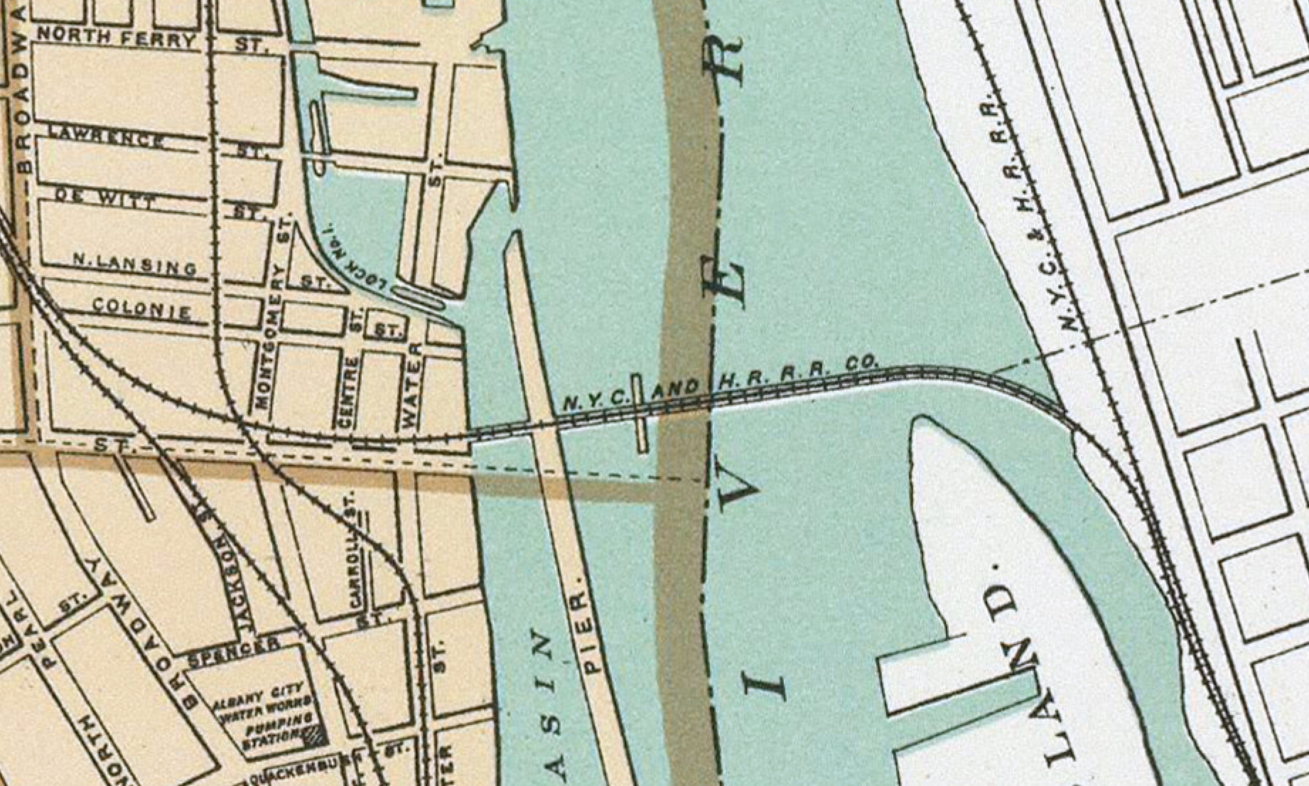
Beginning at a point on the wharf in the city of Albany, on the westerly side or shore of the Hudson river, sixty (60) feet north of the north line of Lumber street in the said city (the said wharf being the westerly line of what is generally known as the Albany Basin), and running thence in a direction south fifty-four (54°) degrees, thirty-five (35) minutes east across the main channel of said river to a point on the island on the easterly side of said main channel, commonly known as Van Rensselaer island, which point is situated one hundred and twelve (112) feet easterly from the front line of the docks on said island and from last mentioned point, running on a line curving southerly with a radius of nine hundred (900) feet to the easterly side or shore of the said river, in the town of Greenbush, Rensselaer county, is the proper place for the construction of said bridge across said river; and I do also hereby further certify and determine that the proper height for said bridge is at least thirty-four and one-half (34-1/2) feet above the lower mitre sill of lock number one of the Erie canal, which lock connects the Erie canal and the Hudson river at the outlet of said canal into the Albany basin, and I do hereby further certify and determine that said bridge, when contracted at the place and height above ascertained and fixed therefor, will be at least twenty-five (25) feet above ordinary common tide water.
Within the report was a description of the history of the Hudson River Bridge at Albany, prepared by chief engineer of the New York Central Railroad, Charles Hilton, Esq., “who, in the early progress of the bridge, aided efficiently in its plans and construction.”
Hilton writes that the bridge crossed about a half mile above the old railroad ferry and linked the New York Central Railroad on the west and the Hudson River, New York and Harlem, and Albany and Boston Railroads on the east. He provides an extensive physical description of the bridge, which follows:
Commencing on the Albany side, the west approach leaves the line of the New York Central Railroad near the corner of Broadway and Colonie streets, curving to the left on a radius of about one thousand (1,000) feet, for a distance of eight hundred sixty-six (866) feet, thence straight three hundred fifty eight (358) feet; thence curving to the left again on a radius of one thousand (1,000) feet, two hundred twenty-one (221) feet, and thence straight, forty-eight (48) feet, total, fourteen hundred ninety-three (1,493) feet, to the west shore of the Albany basin, and beginning of the bridge proper; thence the line is straight, and nearly at right angles to the course of the river across the Albany basin, two hundred (200) feet, Albany pier, seventy-eight (78) feet, and the main channel of the river ten hundred twenty-one (1,021) feet, total, twelve hundred ninety-nine (1,299) feet; thence curving to the right on a radius of nine hundred (900) feet, for a distance of seven hundred seventeen (717) feet, across the flats which spread out at the head of Van Rensselaer’s island, to the east abutment, or end of the bridge proper; thence the line continues curving to the right on about the same radius for five hundred (500) feet over the east approach to the line of the Hudson River Railroad, making the total length of the bridge and approaches, four thousand and nine (4,009) feet, or, over three-fourths of a mile.
APPROACHES.
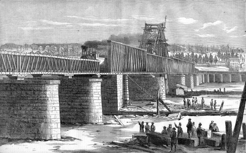
The approaches to the bridge designed ultimately to consist of masonry and embankment, are at present temporarily built of timber trestle work, varying in height from three to twenty feet, with timber truss bridges over Montgomery, Centre and Water streets, on the Albany side. The trestle work on the east side of the river, consists of piles driven in the ground in rows of four each across the line of the track, the rows being eight (8) feet apart, cut off at the proper height and capped with twelve-inch square timber. Upon these caps the stringers are laid, which carry the cross-ties and rails. The trestle work for the western approach is more substantially constructed, being framed in double bents of twelve inch square timber, having their sills imbedded in the ground several feet below the surface, and of sufficient width for a double track. The trestle work of the east approach is intended to be replaced by an embankment during the coming season; while it may be several years before that of the west approach is replaced by more permanent structures.
THE MAIN BRIDGE
Consists of twenty (20) spans, of the following clear widths: three (3) over the Albany basin of sixty-six (66) feet each, four (4) fixed spans of one hundred seventy-two (172) feet each, and two (2) draw spans of one hundred eleven and three-fourths (111-3/4) feet each, over the main channel, and one (1) span of seventy-one feet, and ten (10) spans of sixty-six (66) feet each, across the flats on the east side; and stand about thirty (30) feet clear height above ordinary summer tide level of the river.
THE SUBSTRUCTURE
Consists of twenty-one (21) stone piers, as follows: beginning at the west end, the first pier is on the west shore of the basin, and is thirty-two (32) feet long and six (6) feet thick under the coping; then follow two (2) in the Albany basin, sixty (60) feet long and six (6) feet thick under the coping; the next is a square abutment, about forty-four (44) feet on each side, and located on the west side of the Albany pier, leaving a roadway in front about thirty (30) feet in width; the next pier is in the deepest water of the main channel, and is seventy-two (72) feet long and six and one-half (6-1/2) feet thick under the coping; the next is the pivot pier, thirty-two (32) feet square, on which the draw-bridge swings; then come three more piers in the main channel, of the same dimensions as the one mentioned next before the pivot pier; and after them, ten (10) more on the flats, of the same thickness, but not so long; and lastly, the abutment on the east shore, having wings extending up and down stream, to retain the earth embankment to be built behind it.
The piers and abutments all rest on foundations of spruce piles, from twelve to fourteen inches in diameter, and driven from two and a half (2-1/2) to three (3) feet apart between centers, and as deep into the bed of the river, as they would go (without splintering under the hammer), which was generally from twenty-four (24) to twenty-eight (28) feet below low water level. In preparing the foundations for the masonry, different methods were adopted in different portions of the work. In the case of the pivot pier, and the three main channel piers east of it, the site of each pier was first excavated to a depth of about twenty (20) feet below low water, and of a length and breadth considerably greater than the intended pier, and, after the piles were driven, a strong crib of twelve inch square timber was built around them, the sides of the cribs being kept from spreading by ties of 1-1/8 inch square iron, placed twelve (12) feet apart in each course of timber. The crib was then sunk upon the bottom of the excavation, having been made of sufficient height to bring the top thereof within two feet of low water level. The interior of the crib was then filled with concrete, composed of coarse gravel and hydraulic cement, and the surplus excavation around the cribs filled with loose stone up to within twelve (12) feet of low water, to support the crib and avert any danger from scouring. The piles were then cut off level with the tops of the cribs, and the whole covered with a platform of six-inch plank, upon which the stone work was commenced. For the westernmost pier in the main channel, which is in the deepest water, no excavation was made, but the piles were cut off to a level about a foot above the bed of the river, and the masonry sunk upon them by means of a timber caisson. For each pier in the basin the piles were cut off six (6) feet below low water, a strong platform moored over them, on which the masonry was commenced, and lowered upon the piles by means of screws. For the piers on the flats, east of the main channel, the site of each was excavated to a depth of about three (3) feet below low water, the piles driven as for others, and cut off about one foot below low water. The excavation was then filled around and over the heads of the piles with concrete, about up to low water line, and upon this the masonry was commenced.
The masonry of the piers and abutments is composed of the best quality of limestone of a bluish grey color, from quarries at Amsterdam and Tribes Hill, on the line of the N.Y. Central Railroad, and from Kingston, in Ulster county, and is laid in courses varying in thickness from twelve to thirty inches.
The beds and joints are cut, and the arrises of each stone chipped to a line, but the faces are left rough and undressed, forming what is technically called “rock-faced work.”
The stones in each course are clamped together with strong iron clamps, and each course is secured to the one next above and below by iron dwells. The shape of the ends of the piers in plan is that of a gothic pointed arch, being formed by two circular arcs of sixty (60) degrees each. The up-stream edge or nose of each main channel pier is sloped back at an angle of about thirty (30) degrees from the perpendicular, the better to enable them to resist, break up or turn aside masses of ice or other float
ing bodies. The pivot pier has guards, constructed of stone in the same manner as itself, placed up and down stream at the proper distances to receive the ends of the draw when swung open, and connected with the pivot pier by timber crib work filled with loose stone.
The sides of all the piers and abutments, except the pivot pier and its guards, which are vertical, have a batter of half an inch to a foot, and the tops are coped with large cut flags carefully fitted and clamped together, and projecting nine inches beyond the face on all sides.
SUPERSTRUCTURE.
The superstructure is designed ultimately to be of iron, and to carry a double track, but at present consists of a single track timber bridge, all except the draw spans being on the well known Howe plan.
The trusses of the long spans (172 feet) are twenty-four (24) feet high, and those of the short spans (66 feet) nine (9) feet [sic] high. The needle beams, 7 X 14 inches, rest on the lower chords, and support the running timbers, cross-ties and rails in the usual manner. The clear width between the trusses if fifteen (15) feet.
The draw, designed by Mr. J.W. Adams, the engineer, is on what is known among engineers as the “arch brace plan,” the peculiarity of which consists in having the main supporting braces radiate from the ends of the lower chords to different points in the length of the upper chords, thereby transmitting the weight of the bridge and load directly to the abutments, instead of indirectly through a series of braces, as in most other plans. The ends of the draw when swinging are supported by eight chains composed of iron bars 5X1 inches, extending from the top of a central tower sixty (60) feet high to the ends of the lower chords of the trusses.
The turn-table of the draw consists essentially of a series of seventy (70) rollers, placed between two circular tracks, one being fastened to the masonry of the pivot pier, and the other to the under side of the bridge. The faces of the tracks which are six (6) inches broad, are accurately planed, so as to present no obstacle to the movement of the rollers, which are turned true and smooth. The rollers are twelve (12) inches in diameter, and eight (8) inches long on the face. They are placed in the annular space between two concentric iron rings, and kept at the proper distance by radial bars, which connect the inner ring with a collar fitted to and revolving around a central pivot pin six (6) inches in diameter.
This turn-table, which is wholly of iron, was made by the Boston Machine Company, and is a very creditable piece of work.
The draw, which weighs about 330 tons, can be opened and closed by five men in about five minutes.
GRADES.
Beginning at the west end of the west approach, the track rises at the rate of twenty (20) feet to the mile, for a distance of seven hundred fifty (750) feet to Montgomery street, where it crosses over the Albany branch of the Rensselaer and Saratoga Railroad, and from thence descends at the rate of thirty (30) feet per mile to the west end of the bridge proper. Across the main channel is grade level, but from the east side thereof it descends at the rate of thirty-five (35) feet per mile to the Hudson River Railroad.
Of course, we’ve given some other parts of the history of the Hudson River Bridge, later known as the North Bridge, and today known as the Livingston Avenue Bridge; you can find it here. While the substructure discussed here still exists and dates to 1866, the superstructure of the bridge was replaced about 1902.
Is there any effort to preserve the Livingston Avenue bridge in place? This would of course require that the new bridge were built sufficiently north of the Livingston Avenue bridge, and (I assume) that an attendant were maintained in the bridge house during boating season.
I can’t imagine the plan is to retain the old bridge, but I haven’t studied the plan documents.
https://www.governor.ny.gov/news/governor-hochul-announces-major-milestone-transformative-livingston-avenue-bridge-replacement
But somewhere in the environmental assessment is this statement on mitigation of impacts: “NYSDOT will also actively seek new ownership of the existing Livingston Avenue Bridge for adaptive reuse, or, because of its overall size, partial reuse at a new location.”
https://www.dot.ny.gov/portal/page/portal/content/delivery/Main-Projects/193549-Home/193549-Repository/LAB-EA_2022_00-Executive-Summary.pdf